Error Analysis

The Arrow From Engineering to Manufacturing

Dissecting the operational confusion created when a single directional line spans organizational and technical boundaries.

The Two-Box Dilemma Across Domain Boundaries

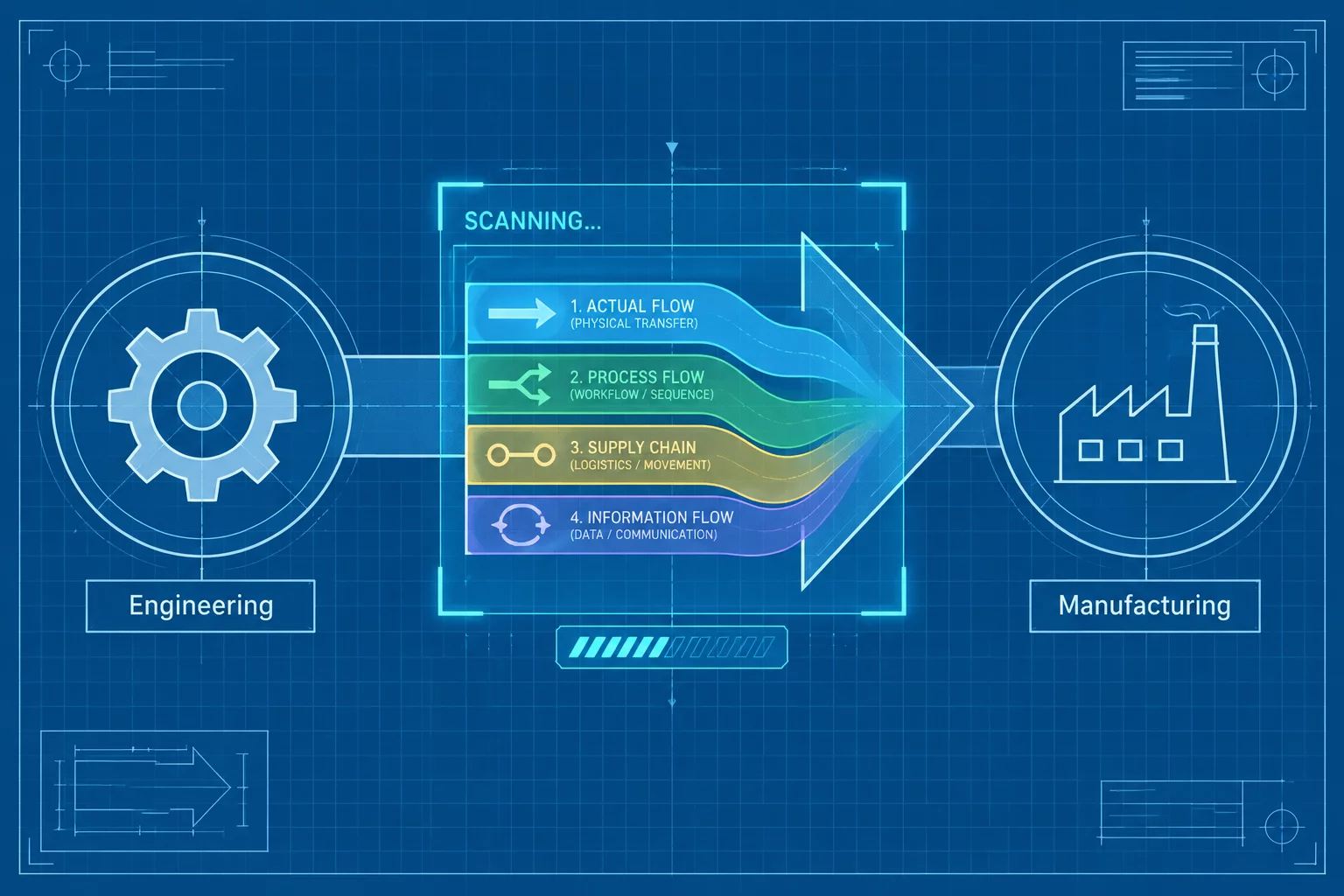
During an operational audit at an industrial equipment manufacturer, a high-level system overview displayed two clean rectangles: Engineering on the left and Manufacturing on the right, joined by a single solid black arrow. Executives praised the diagram for its simplicity. On the factory floor and inside engineering sprints, however, this single connector sparked recurring schedule slips, duplicate work, and conflicting release assumptions.

Leadership looked at the connector and assumed it designated a formal waterfall handover of design ownership. The manufacturing team assumed it represented an automated pipeline pulling real-time bill-of-materials revisions directly into their ERP. Meanwhile, quality managers treated the line as a mandatory sign-off checkpoint before production tooling could run. Because the arrow lacked an explicit semantic predicate, every team projected their own workflow onto that single line.

Diagnostic Framework: Two Nodes to Clear Meaning

When two major departmental nodes connect through a generic arrow, ask: What physical or digital artifact moves? Is the interaction synchronous or asynchronous? Does the arrow denote sequence, data flow, permission gate, or continuous synchronization?

When diagrams fail to differentiate between physical material movement, digital data transfers, and governance gates, organizational execution degrades. Resolving the ambiguity requires analyzing the operational evidence and replacing the blanket arrow with distinct, semantically grounded relations.

Four Conflicting Realities in One Arrow

Investigating how different stakeholders interpreted the connection revealed four mutually exclusive operational models simultaneously attached to one drawn line:

  1. A
    Interpretation A — Handoff

    Engineering transfers released information to Manufacturing. The arrow marks a one-time delivery point where finished designs leave engineering responsibility.

  2. B
    Interpretation B — Approval

    Manufacturing must approve the design before release. The arrow represents an authority gate, not a transfer — production cannot start until the review formally passes.

  3. C
    Interpretation C — Feedback

    Manufacturing sends process constraints back to Engineering. Read this way, the arrow runs opposite to the assumed direction — tooling limits and material realities flow upstream into design decisions.

  4. D
    Interpretation D — Ownership Transfer

    After a defined stage, responsibility for the artifact passes to a different group. The arrow denotes a change of ownership, not the movement of any information or material.

Case Questions: What the Arrow Must Answer

Before assigning any visual treatment to the connector, the team had to resolve seven diagnostic questions about what the relationship actually is:

  • What exactly moves between the two nodes?
  • Is the relationship one-way or reciprocal?
  • Does the arrow describe sequence, dependency, authority, or information flow?
  • Who initiates the relationship?
  • Does anything need to happen before the connection becomes active?
  • Would a text label remove the ambiguity?
  • Would two separate connectors be more accurate than one bidirectional arrow?

Remediating the Ambiguous Edge

Eliminating cross-team confusion did not require cluttering the architectural diagram with dozens of tiny boxes. The solution came from establishing strict connector semantics across the diagramming standards.

The team split the original relationship into two distinct layers: an upper governance row showing milestone authorizations with condition badges, and a lower data-plane flow showing automated ERP synchronization with explicit protocol labels. Solid arrows now carry explicit directional verbs, while conditional approvals use distinct gate markers.

By clarifying whether an edge transmits information, demands authorization, or triggers execution, technical teams eliminate subjective interpretation. The resulting system map provides an unambiguous blueprint that both software engineers and plant supervisors can execute against without friction.

The Takeaway

Not: "Use a dashed arrow here."

But: "First define the relationship. Then choose the visual treatment that represents it."

Topic Tags: Handoff vs Flow Error Analysis Cross-Functional Alignment Predicate Precision

Stay Informed on Diagram Semantics

Receive practical case studies, notation standards, and structural disambiguation guides directly in your inbox.

Related Semantic Studies

Continue exploring diagrammatic accuracy, connector disambiguation, and edge classification.