Notation Basics

A Dependency Is Not the Same as a Sequence

Why mixing temporal execution order with structural prerequisites creates architectural ambiguity and misleading process designs.

The Fundamental Divergence of Time and Structural Reliance

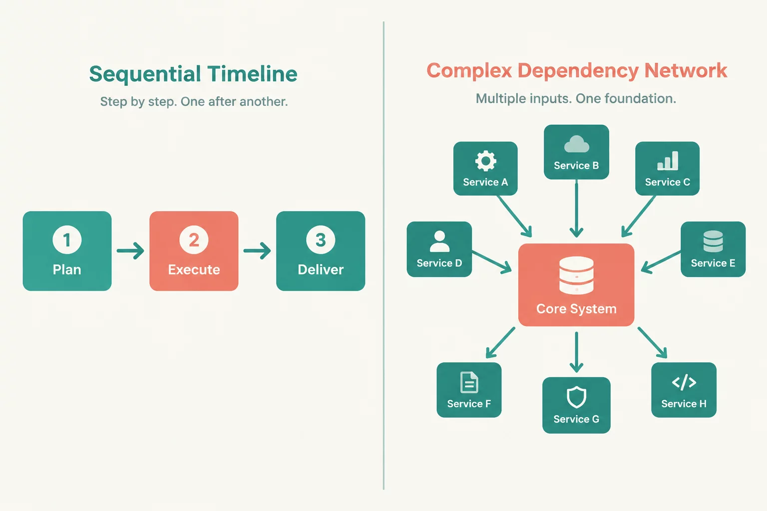
Technical diagrams routinely collapse two distinct conceptual dimensions into a single directional arrow. One dimension tracks the chronological progression of steps across a timeline, whereas the other establishes an architectural prerequisite where one module cannot exist or execute without another. When engineers depict both using identical lines, readers immediately conflate sequential timing with structural coupling.

In an execution sequence, Step B occurs strictly after Step A finishes, yet Step B may possess zero structural reliance on Step A. Conversely, Service Y can depend entirely on Service X for initial configuration, yet both run simultaneously as long-lived daemon processes from system startup. Assuming that chronological order implies dependency causes engineers to build brittle architectures around false serialization assumptions.

The Core Diagnostic Rule

A sequence answers the question "What happens next in chronological time?" whereas a dependency answers "What must exist for this component to operate at all?"

When both relationships share an identical line style, reviewers cannot determine whether removing an upstream node prevents compilation or merely adjusts the order of asynchronous event dispatching.

Four Recurring Failure Modes in Practice

Ambiguity between dependency and sequence lines creates concrete engineering misunderstandings across systems design and operations:

  1. 01
    Inverted Arrow Directionality

    Sequence connectors point forward in time toward the successor node, while dependency connectors in standard notations point toward the prerequisite provider. Mixing these conventions leads readers to interpret consumer-provider contracts backwards.

  2. 02
    Phantom Serialization Bottlenecks

    When independent services are connected with sequence-like arrows to indicate data requirements, operations teams schedule them sequentially, destroying parallel processing potential and adding latency.

  3. 03
    Concealed Runtime Couplings

    Drawing a simple "next step" arrow masks heavy synchronous RPC couplings, hiding single-point-of-failure vulnerabilities during incident reviews and outage post-mortems.

  4. 04
    Miscalculated Refactoring Blast Radius

    Developers assuming an arrow only implies handoff timing often delete or modify upstream schemas without realizing downstream compile-time bindings rely on structural interfaces.

Establishing Semantic Disambiguation

Solving this confusion does not require complex proprietary notations; it demands consistent edge semantics and disciplined visual grammar across all technical documentation.

A robust convention applies solid lines with filled directional arrowheads solely for temporal flow and process sequences, annotated with active verb phrases such as "triggers", "transitions to", or "dispatches". In contrast, structural dependencies should utilize open-arrow dashed lines or nested container boundaries, labeled with stateful requirement terms such as "depends on", "imports", or "binds interface".

Separating temporal sequence diagrams from static component topologies also prevents cognitive overloading. When both dimensions must share a single canvas, clear legend keys and unambiguous relational verbs eliminate guesswork for cross-functional teams.

Topic Tags: Diagram Semantics Sequence vs Dependency Architecture Modeling Notation Clarity

Master Diagrammatic Precision

Subscribe to our research briefs for insightful breakdowns on connector semantics, visual modeling antipatterns, and diagram clarity standards.

Related Semantic Studies

Continue exploring diagrammatic accuracy, connector disambiguation, and edge classification.